This post walks through a centralized firewall inspection architecture on AWS using Transit Gateway, AWS Network Firewall, and a hub-and-spoke VPC design. All egress, ingress, and east-west traffic between spoke VPCs routes through a single inspection VPC where Network Firewall applies stateful rules (domain blocking, alerting, tag-based bypass). A shared Endpoints VPC provides centralized VPC Interface Endpoints with Route 53 Private Hosted Zones for cross-VPC DNS resolution. A Lambda + EventBridge system provides tag-based firewall bypass for instances that need to skip inspection. The entire stack is defined in Terraform. This post focuses on architecture, traffic flows, and design decisions - not a line-by-line code walkthrough.
Why Centralized Inspection?
In a multi-VPC environment, you have a few options for traffic inspection:
| Approach | Pros | Cons |
|---|---|---|
| Firewall per VPC | Simple, isolated blast radius | Expensive (per-endpoint charges multiply), policy duplication, operational overhead |
| Centralized inspection VPC | Single policy, single pane of glass, cost-efficient | More complex routing, single point of inspection |
| Third-party appliance (Palo Alto, Fortinet) | Mature feature sets, vendor support | Licensing costs, GWLB complexity, operational overhead |
A centralized inspection VPC hits the sweet spot for most organizations: one set of firewall rules, one place to look at logs, and one architecture to maintain. The tradeoff is routing complexity, which this post addresses.
Architecture Overview
The architecture has four VPCs connected via Transit Gateway:
| VPC | CIDR | Purpose |
|---|---|---|
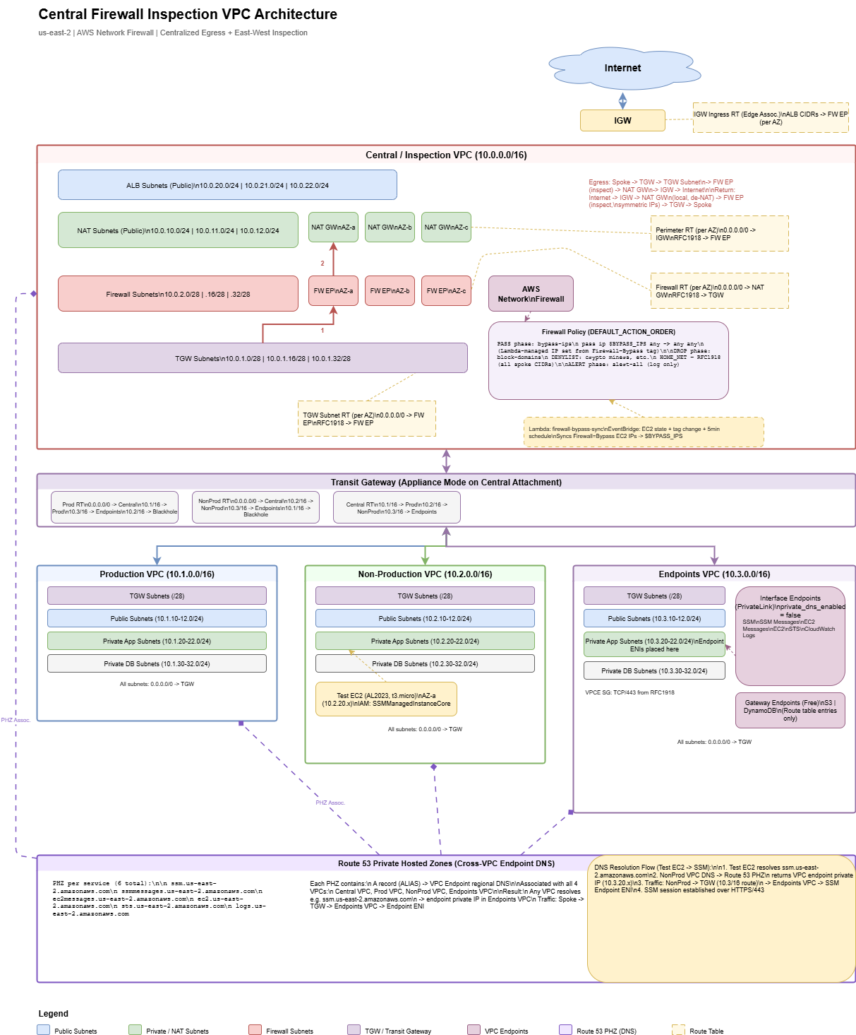
| Central / Inspection | 10.0.0.0/16 | Network Firewall, NAT Gateways, ALB subnets, TGW attachment |
| Production | 10.1.0.0/16 | Production workloads (app, DB, public tiers) |
| Non-Production | 10.2.0.0/16 | Dev/staging workloads (same tier structure as Prod) |
| Endpoints | 10.3.0.0/16 | Shared VPC Interface Endpoints (SSM, STS, CloudWatch Logs, etc.) |
Central Inspection VPC: Subnet Tiers
The central VPC has four subnet tiers, each in three AZs. Understanding why each tier exists is key to understanding the routing:
| Tier | CIDRs (per AZ) | Role |
|---|---|---|
| TGW Subnets | 10.0.1.0/28, .16/28, .32/28 | Transit Gateway ENIs land here. First hop for all spoke traffic entering the central VPC. |
| Firewall Subnets | 10.0.2.0/28, .16/28, .32/28 | Network Firewall endpoints live here. All traffic routes through these for inspection. |
| NAT Subnets | 10.0.10.0/24, .11.0/24, .12.0/24 | NAT Gateways with Elastic IPs. Inspected traffic gets source-NATed here before exiting to the internet. |
| ALB Subnets | 10.0.20.0/24, .21.0/24, .22.0/24 | Public-facing Application Load Balancers for inbound traffic (internet → spoke). |
You might be tempted to put the TGW attachment and the firewall endpoint in the same subnet. Don't. Route tables are associated per-subnet, and you need different routing behavior for traffic arriving from TGW (route to firewall) vs. traffic leaving the firewall (route to NAT or back to TGW). Separate subnets = separate route tables = clean traffic flow.
Transit Gateway Design
The Transit Gateway connects all four VPCs and controls which VPCs can talk to each other.
Key Design Decisions
- Appliance mode enabled on the central VPC attachment. Without this, TGW can route return traffic to a different AZ than the request, breaking stateful firewall inspection. Appliance mode ensures symmetric routing through the same firewall endpoint.
- Default route table association/propagation disabled. Manually managed route tables give you full control over traffic isolation.
- Three TGW route tables: Production, Non-Production, and Central. Each spoke is associated with its own route table.
TGW Route Table Isolation
This is where environment isolation happens:
| Route Table | Associated VPC | Routes |
|---|---|---|
| Prod RT | Production VPC | 0.0.0.0/0 → Central (inspection + NAT), Endpoints VPC → direct, Non-Prod → blackhole |
| Non-Prod RT | Non-Production VPC | 0.0.0.0/0 → Central (inspection + NAT), Endpoints VPC → direct, Prod → blackhole |
| Central RT | Central VPC + Endpoints VPC | Routes to all spoke VPCs (return path for inspected traffic) |
The blackhole routes are the isolation mechanism - Prod cannot reach Non-Prod and vice versa, enforced at the TGW routing layer. The Endpoints VPC is reachable from both because it hosts shared services.
You could achieve isolation by simply not adding a route (traffic would be dropped anyway). Explicit blackhole routes are better because they show up clearly in route table views and make the isolation intentional and documented. Pick the approach that fits your operational model.
Traffic Flows
Understanding the routing is the hardest part of this architecture. There are three distinct traffic flows, each with different route table chains.
Egress: Spoke → Internet
Spoke Instance
  → Spoke RT: 0.0.0.0/0 → TGW
  → TGW Prod/NonProd RT: 0.0.0.0/0 → Central VPC attachment
  → TGW Subnet RT: 0.0.0.0/0 → Firewall Endpoint (inspection)
  → Firewall Subnet RT: 0.0.0.0/0 → NAT Gateway (source NAT)
  → Perimeter RT: 0.0.0.0/0 → Internet Gateway
  → Internet
Five route table hops from spoke to internet. Each hop serves a purpose: TGW routing, firewall inspection, NAT, and internet exit.
Return: Internet → Spoke
Internet
  → IGW → NAT Gateway (de-NAT, local route)
  → Perimeter RT: RFC1918 → Firewall Endpoint (stateful return inspection)
  → Firewall Subnet RT: RFC1918 → TGW
  → TGW Central RT → Spoke VPC attachment
  → Spoke Instance
The return path is symmetric through the firewall thanks to appliance mode. The perimeter route table sends de-NATed RFC1918 traffic back through the firewall, which matches the original connection state and allows the return.
East-West: Spoke A → Spoke B
Spoke A Instance
  → Spoke A RT: 0.0.0.0/0 → TGW
  → TGW Prod/NonProd RT: 0.0.0.0/0 → Central VPC attachment
  → TGW Subnet RT: RFC1918 → Firewall Endpoint (inspection)
  → Firewall Subnet RT: RFC1918 → TGW
  → TGW Central RT → Spoke B VPC attachment
  → Spoke B Instance
East-west traffic hairpins through the central VPC: in through TGW, inspected by the firewall, back out through TGW to the destination spoke. The RFC1918 routes on the TGW subnet route table send private traffic to the firewall, while the firewall route table sends it back to TGW after inspection.
For inbound internet traffic to ALB subnets, an IGW edge-associated route table routes ALB subnet CIDRs to the firewall endpoint (per AZ). NAT subnet CIDRs are not included here - egress return traffic goes directly to the NAT Gateway via local route, then the perimeter route table sends it through the firewall. This avoids double-inspecting return traffic and keeps the stateful session tracking intact.
AWS Network Firewall Configuration
The firewall uses DEFAULT_ACTION_ORDER for the stateful engine, which evaluates rules in a fixed order:
PASS → DROP → REJECT → ALERTThis ordering is automatic - you don't set priorities on rule groups. Rules with a PASS action always evaluate before DROP, which always evaluates before ALERT. This is important for the bypass mechanism.
Rule Groups
| Rule Group | Action | Purpose |
|---|---|---|
| bypass-ips | PASS | IP set variable $BYPASS_IPS - tagged instances skip all inspection |
| block-domains | DROP | Domain denylist (crypto miners, malware C2, etc.) matching on HTTP_HOST and TLS_SNI |
| alert-all | ALERT | Catch-all rule that logs all traffic for visibility (pass-through) |
Because PASS evaluates first, bypass IPs skip the domain blocking entirely. The alert-all rule runs last and provides a log of everything that wasn't dropped.
HOME_NET Override
By default, Network Firewall sets HOME_NET to the firewall VPC CIDR only (10.0.0.0/16). Since spoke traffic comes from 10.1.x.x or 10.2.x.x, it wouldn't match the generated Suricata rules. The block-domains rule group overrides HOME_NET to include all RFC1918 ranges:
rule_variables {
  ip_sets {
    key = "HOME_NET"
    ip_set {
      definition = ["10.0.0.0/8", "172.16.0.0/12", "192.168.0.0/16"]
    }
  }
}
Without this override, your domain blocking rules will silently pass spoke traffic. This is one of those gotchas that costs hours to debug.
Tag-Based Firewall Bypass
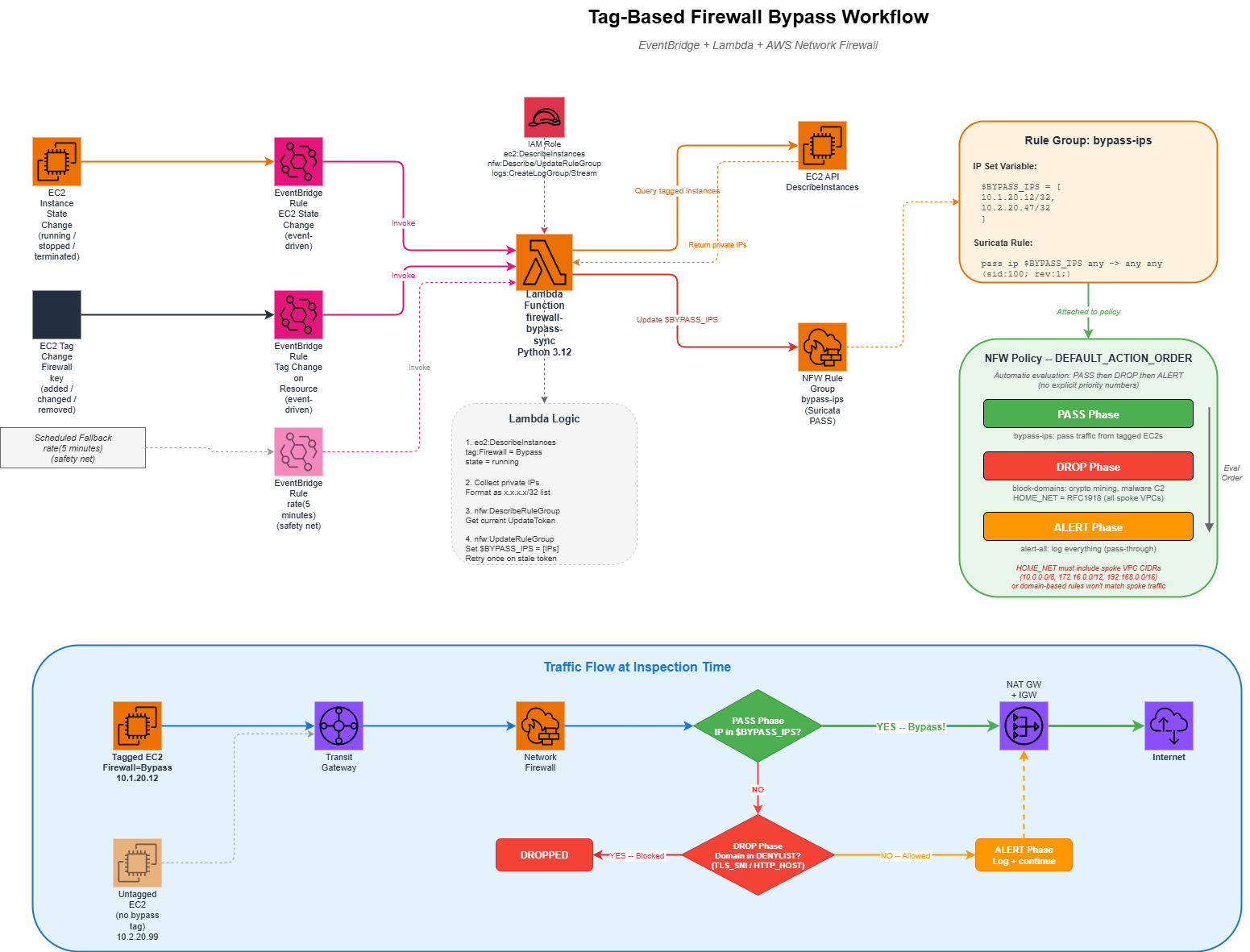
Sometimes instances need to bypass the firewall - maybe a legacy app breaks with TLS inspection, or a service needs unrestricted access during a migration window. Rather than managing static IP lists, this architecture uses a tag-driven approach:
- Tag an EC2 instance with
Firewall=Bypass - EventBridge detects the tag change (or instance state change)
- A Lambda function queries all running instances with the tag
- Lambda updates the Network Firewall rule group's
$BYPASS_IPSvariable - The PASS rule in DEFAULT_ACTION_ORDER evaluation skips inspection for those IPs
EventBridge Triggers
Three triggers ensure the bypass list stays current:
| Trigger | Event | Why |
|---|---|---|
| EC2 State Change | running / stopped / terminated | Add or remove IPs when instances start or stop |
| Tag Change | Firewall tag modified |
React when someone adds or removes the bypass tag |
| Scheduled (5 min) | Periodic | Safety net to catch any missed events |
How the Lambda Works
The Lambda function is straightforward:
- Query EC2 for all running instances tagged
Firewall=Bypass - Collect their private IPs as /32 CIDRs
- If no bypass instances exist, fall back to
127.0.0.1/32(placeholder - IP set variables can't be empty) - Update the NFW rule group's IP set variable using the describe/update token pattern
The bypass rule group uses lifecycle { ignore_changes = [rule_group] } so Terraform doesn't overwrite the IP set that Lambda manages. Without this, every terraform apply would reset the bypass list back to the placeholder. This is a common pattern when Terraform creates a resource but another system manages its runtime state.
Shared VPC Endpoints
Instead of creating VPC endpoints in every spoke VPC (which gets expensive with interface endpoints at ~$7.50/AZ/month each), a dedicated Endpoints VPC hosts them centrally.
Endpoint Types
| Type | Services | Cost |
|---|---|---|
| Gateway | S3, DynamoDB | Free (route table entries only) |
| Interface | EC2, SSM, SSM Messages, EC2 Messages, STS, CloudWatch Logs | ~$7.50/AZ/month per endpoint + data processing |
Cross-VPC DNS Resolution
The tricky part with centralized endpoints is DNS. When an EC2 instance in the Prod VPC calls ssm.us-east-2.amazonaws.com, it needs to resolve to the private IP of the endpoint ENI in the Endpoints VPC, not the public IP.
The solution uses Route 53 Private Hosted Zones:
- Set
private_dns_enabled = falseon the interface endpoints (to avoid the one-VPC-only limitation) - Create a PHZ for each service (e.g.,
ssm.us-east-2.amazonaws.com) - Add alias A records pointing to the endpoint's regional DNS name
- Associate the PHZ with all VPCs (central, prod, nonprod, endpoints)
Now any instance in any VPC resolves service DNS names to the private endpoint IPs. Traffic flows through TGW to the Endpoints VPC and hits the endpoint ENIs directly - no internet transit, no NAT, no firewall inspection needed for AWS API calls.
Instead of PHZs, you could use Route 53 Resolver forwarding rules to forward service DNS queries to the Endpoints VPC's DNS resolver. The PHZ approach is simpler and doesn't require Resolver endpoints (which have their own per-ENI costs). Evaluate which approach fits your DNS architecture.
Spoke VPC Design
Each spoke VPC follows a consistent four-tier subnet layout across three AZs:
| Tier | Purpose | Routing |
|---|---|---|
| TGW | Transit Gateway ENIs | Local only (no custom routes) |
| Public | Internet-facing resources | 0.0.0.0/0 → TGW (no local IGW) |
| App | Application servers | 0.0.0.0/0 → TGW |
| DB | Databases | 0.0.0.0/0 → TGW |
Every subnet's default route points to TGW. There is no IGW or NAT Gateway in the spoke VPCs - all internet access is centralized through the inspection VPC. This is what forces all traffic through the firewall.
Spoke VPCs have no IGW. This means that even "public" subnets don't have direct internet access - all traffic routes through TGW to the central VPC for inspection and NAT. If you need true public subnets with direct internet access in a spoke (e.g., for a public-facing ALB), you'll need to add an IGW and modify the routing. Think about whether centralized ALBs in the inspection VPC work for your use case instead.
Design Decisions to Consider
This architecture makes certain choices. Here are the tradeoffs you should evaluate for your own environment:
Single Region vs. Multi-Region
This design is single-region. For multi-region, you'd need a TGW in each region with inter-region TGW peering, and a decision on whether to inspect cross-region traffic locally or route it to a central region. There's no single right answer - it depends on your latency tolerance and compliance requirements.
NAT Gateway per AZ vs. Shared
This architecture deploys one NAT Gateway per AZ ($32/month each, plus data processing). For cost-sensitive environments, you could use a single NAT Gateway and accept the cross-AZ data transfer charges and reduced availability. Run the numbers for your traffic volume.
Network Firewall vs. Third-Party Appliance
AWS Network Firewall is a managed Suricata-based service. It handles basic domain filtering and IP-based rules well. If you need deep packet inspection, application-layer awareness, URL filtering, or threat intelligence feeds, evaluate whether a third-party appliance behind a Gateway Load Balancer better fits your requirements. The routing architecture in this post works with either approach - you'd replace the Network Firewall endpoints with GWLB endpoints.
Strict vs. Default Action Order
This architecture uses DEFAULT_ACTION_ORDER (automatic PASS → DROP → ALERT ordering). The alternative is STRICT_ORDER, where you explicitly set numeric priorities on each rule group. Strict order gives you finer control but is harder to reason about. Default order is simpler when your rule groups fall cleanly into pass/drop/alert categories.
Endpoints VPC vs. Endpoints Per VPC
Centralizing endpoints saves cost (one set of interface endpoints shared across all VPCs) but adds the DNS complexity of PHZs and the network hop through TGW. For a small number of VPCs, per-VPC endpoints might be simpler. For 5+ VPCs, centralized endpoints almost always win on cost.
Bypass Mechanism: Tags vs. Static IPs vs. Separate Route
The tag-based bypass is flexible but introduces a Lambda dependency. Alternatives:
- Static IP list in the rule group - simpler, but manual updates
- Separate TGW route table that routes directly to NAT (bypassing the firewall subnet entirely) - more routing complexity, but no Lambda needed
- No bypass - simplest and most secure, but inflexible
On-Premises Connectivity
The variables include an on_prem_cidrs placeholder for future Direct Connect or VPN connectivity. When you're ready, you'd add a VPN or DX attachment to the TGW, create routes in the appropriate TGW route tables, and decide whether on-prem traffic should also be inspected by the firewall or bypass it.
What You'll Need
If you're building something similar, here's a checklist of the AWS services involved:
- Transit Gateway with appliance mode support
- AWS Network Firewall (or GWLB + third-party appliance)
- NAT Gateways with Elastic IPs (per AZ in the central VPC)
- VPC Interface Endpoints for AWS services your workloads use
- Route 53 Private Hosted Zones for cross-VPC endpoint DNS
- Lambda + EventBridge (if using tag-based bypass)
- IAM roles for Lambda (EC2 describe + NFW update) and test EC2 (SSM access)
The Terraform files are organized by concern: vpc.tf, firewall.tf, tgw.tf, route-tables.tf, spoke-prod.tf, spoke-nonprod.tf, spoke-endpoints.tf, firewall-bypass.tf. Each file is self-contained and can be adapted independently to your naming conventions, CIDR ranges, and AWS account structure.
Cost Considerations
This architecture has several cost components you should estimate before deploying:
| Component | Approximate Monthly Cost | Notes |
|---|---|---|
| Network Firewall endpoints (3 AZs) | ~$262 | $0.395/endpoint/hour |
| Network Firewall data processing | Variable | $0.065/GB |
| Transit Gateway attachments (4 VPCs) | ~$144 | $0.05/attachment/hour |
| Transit Gateway data processing | Variable | $0.02/GB |
| NAT Gateways (3 AZs) | ~$97 | $0.045/hour + $0.045/GB |
| Interface Endpoints (6 services x 3 AZs) | ~$135 | $0.01/hour/ENI + $0.01/GB |
| Lambda invocations | ~$0 | Free tier covers this easily |
Baseline infrastructure cost: ~$640/month before data processing. This covers all four VPCs, the firewall, TGW, NAT, and shared endpoints. Data processing charges scale with your traffic volume.
Compare this against deploying Network Firewall, NAT Gateways, and VPC endpoints in each spoke VPC individually - the centralized approach typically saves 40-60% on infrastructure costs at 3+ VPCs.
Want Help With This?
If you're working on something similar and want a second set of eyes, or you'd like to talk through how this applies to your environment, reach out via the contact form. Happy to help.